|
To reduce soft sync, either of these mods works. However, I
have not tested the TTL subharmonic generator with the CMOS 7555.
The CMOS subharmonic generator will work fine with it.
|
More Simple Stuff
The Lee Diode Modification
The Lee Diode modification, named after Scott Lee, is extremely
simple and by itself greatly reduces soft sync. Soft sync is
the property of oscillators on a common power supply to
synchronize when brought close together harmonically. One
of the sonically interesting things about having 2 oscillators is
bringing them very close together in pitch and listening to the
'beat' sound. This modification allows the FatMan's oscillators to run much
closer together in pitch before locking.
The modification involves removing R38 and R39 and
replacing them with (identical) LEDs. The arrow must point away
from pin 1 of the 555 to which it is attached. I did this by
looking at the copper side of the board and following the trace
from pin 1 of the 555 IC. It won't hurt it to accidentally
solder the LED backwards. It just won't work.
That's it. If done correctly, the LEDs should light solidly
as long as power is applied.
You can improve this by putting another 100 uF (same voltage rating)
cap in parallel with the ones that are already bypassing the 555s.
Remember to respect the cap's polarity. This increases the bypass
capacitance to 200uF each 555.
My own insight on this is that the diode (LED) and the bypass cap provides
a mini-power supply for each 555 timer. The diode (LED) isolates the 555
chip better than the 10 ohm resistor. The whole problem stems from the
fact that the 555 pin 3 output is from a bipolar transistor totem pole.
When this output changes changes state, both transistors are on at the same
time for an instant. During this instant, the supply pin is shunted close
to ground through the totem pole transistors, causing causing a noise
impulse on the supply line and ground. This impulse can have an effect on other
circuits attached to that power supply, including the other VCO.
Replace the 555 timers
Replace the 555 timers (IC15 & IC16) with type ICM7555. It is a CMOS part that does not
crowbar the power supply when it resets as the bipolar 555 does. This
drastically reduces softsync. The parts are pin for pin compatible.
Separate Level Controls for the VCOs
Recently, I added an external input and I needed to be able to
control each VCO level separately in order to be able to balance
them against the external input. Originally, my circuit had two
level controls that passed their respective signal to the 1/2 mix
pot. Since this pot was always centered, it was actually
redundant. I then decided to remove it from the circuit and run
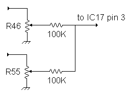
each VCO signal thru it's own 100K summing resistor to the VCF.
A happy consequence of this was (apparently) better isolation of
the VCOs, because now, I can get them much closer together
without locking. I can now get them within about 1/12 of a hertz
before they lock.
|
This image depicts the FatMan modification to
further isolate the VCOs. Feed your external input
through a 100 K resistor into pin 3 of IC17.
The external input requires a preamp to provide a fairly
large signal (8 volts p-p) I used an op-amp for that.
|

|
Remove R46, R55 and R57. Disconnect R56 (1/2 mix pot). Replace
R46 and R55 each with a 10K pot. You can use R56 for one of
these if desired. Point A comes from the positive side of C15.
There is a convenient connection hole left by the removal of R46.
Point B comes from the positive side of C18. There is a
convenient connection point left by the removal of R55. Add in
the 2 new 100K resistors as shown above. Pin 3 of IC 17 may be
accessed using the convenient connection hole left by the removal
of R57.
Knob Mods
Here are a couple of easy 'knob mods'. A few of the FatMan knobs
have some "user protection" features built in. I call it
"Idiot Proofing". Anyway, it amounts to a resistor in series with
a pot so that you can't completely cut off that feature.
- Pitch Knob, Extend Low End ... R35:
As supplied this is 1K. I shorted it. You can either short it (or use a switch to short it)
or you can reduce it. R35 limits the lowest frequency available from the VCOs.
If you short it, the VCOs can go much lower in pitch.
Be Warned: When turned all of the way
down, you may hear nothing at all.
- VCF Cutoff "Freq" Knob, Extend Low End ... R73
As supplied this is 100 ohms. I shorted it. It limits the low frequency end of this setting
for the filter.
Be Warned: When turned all of the way
down, you may hear nothing at all.
- Add a Resonance Max Switch
Break the connection between R114 (rez pot) and Wire "J". Insert SPST Switch Here. When the switch
is closed, all is normal. When open, the resonance jumps to its absolute maximum. The switch is
opening the negative feedback loop so that there is no negative feedback at all.