I get many questions about bits and pieces of the FatMan, what they
are, where they are, what they do, etc. I will try to keep this page
up to date with the more commonly asked questions.
- • How can I add signals,
such as noise to a FatMan?
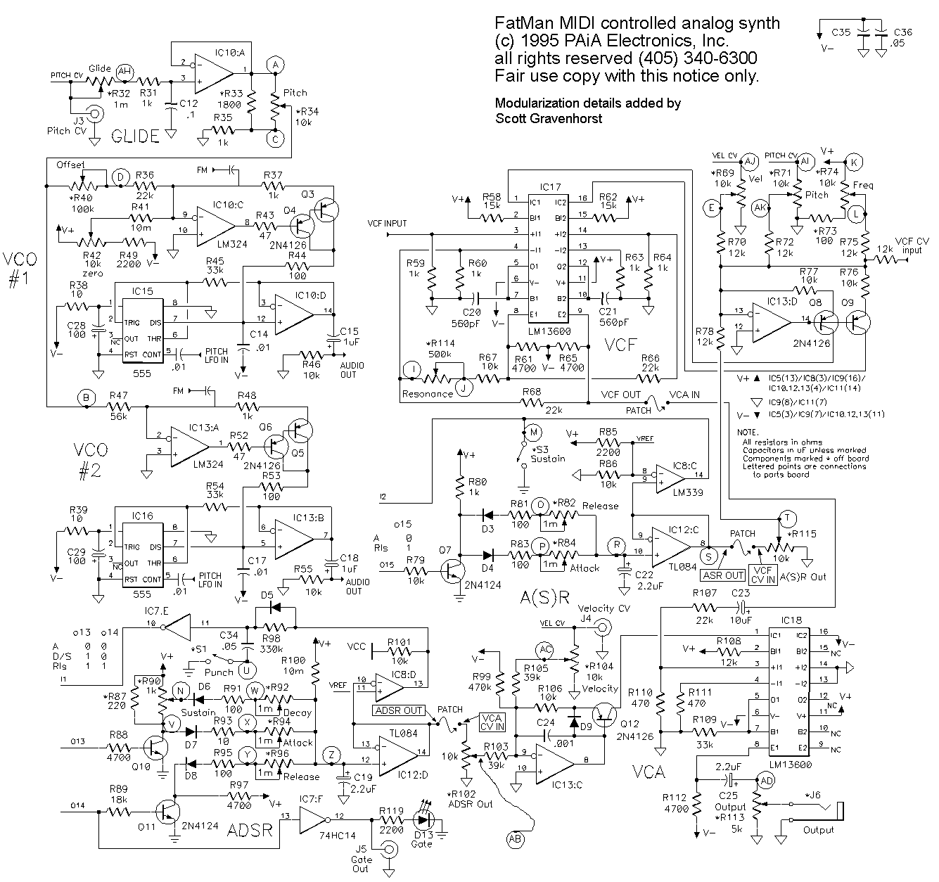
- Assuming that you want a signal mixed with the VCOs,
you want to inject your signal into the input of the VCF.
This is pin3 of IC 17. Always run your signal through a
resistor to this pin. A look at the schematic shows that
the VCOs, which are capable of an 8 volt (AC) signal are run
through a 100K resistor. If your signal is smaller, use
an appropriately smaller resistor. Ultimately,
experimentation may be the best way to determine the exact
proper value. A word of slight caution, if you add many
things, then you run into a possible distortion problem,
and it is worth looking at the
FatMixer as a solution to
better controlling signals added to the FatMan VCF input.
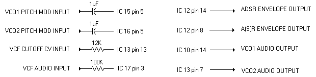
- • How can I add my own modulation control voltages to the VCF?
- A zero to 6.55 volt CV can be mixed with the existing CV signals
by routing the new signal through a 12K resistor to pin 13 of IC 13.
- • How can I add my own modulation control voltages to the VCA?
- A zero to 6.55 volt CV can be mixed with the existing CV signals
by routing the new signal through a 39K resistor to pin 9 of IC 13.
- • What are the usable outputs from the VCO?
- IC 18 pin 14 and IC 13 pin 7 are the buffered ramp outputs, with the DC
ramp starting at -12v and reaching -4v just before reset. Pin 3 of
IC 15 and pin 3 of IC 16 provides a narrow -12 volt pulse.
- • What other outputs are there?
-
| • Buffered pitch CV: | | IC 10 pin 1 (wire A) |
| • Buffered ASR CV: | | IC 12 pin 8 (wire S) |
| • Buffered ADSR CV: | | IC 12 pin 14 (wire AA) |
| • Buffered Sawtooth: | | IC 10 pin 14 & IC 13 pin 7. 8 volts P-P. |
| • ASR Gate (not TTL): | | Q7 Collector |
| • ADSR AD Gate (not TTL): | | Q10 Collector |
|