|
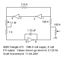
This LFO is made from 1/2 of a 4069. You can make a dual LFO by using the whole chip. This could be powered from 8 volts and ground on the FatMan. Actually, it can also be powered from ground and -12v. It can also be powered by a bipolar supply, but the data sheet says +/- 7.5 volts is recommended. However they also state that +/- 9 is the absolute max (you'll burn it out). I am going to experiment with +/- 8 volts. It will be alot easier to use these CMOS chips with a FatMan if it works. I had the cycle time down to 150 seconds per cycle with a 22 meg resistor in series with the rate pot. Also, the rate pot (the one meg pot) should be a log type. You can range switch larger caps in if you want to. I would also suggest a larger pot - more range. Easily 10 meg sould be used. And making the cap larger will slow it down even more. The output voltage is more or less a triangle waveform and is almost rail to rail, whatever they are. I say "more or less" because the ramps are really "S" curved a bit due to the way the CMOS inverters distort when used as linear amplifiers. This makes the waveform a combination of sine and triangle and I find it quite nice. Run it from +8v and ground and it will easily modulate the filter. To LFO modulate the pitch of the VCO, it's easy to use pin 5 of the 555. Trying to do FM at pin 5 doesn't work because this only changes the oscillator's reset threshhold and not the cap charging current. It does work pretty well for LFO modulation. The LFO can also run from ground and -12v and then it's easy to modulate the VCO using pin 5. If you really need true triangle, you can use the ASM-1 design from which this was adapted. The ASM-1 uses opamps instead of CMOS inverters. If you want a more sine-like wave form, you can use CMOS inverters in linear amplifier mode to further process the signal. This causes even more S curving of the ramps and gets very close to sine if adjusted correctly. |