|
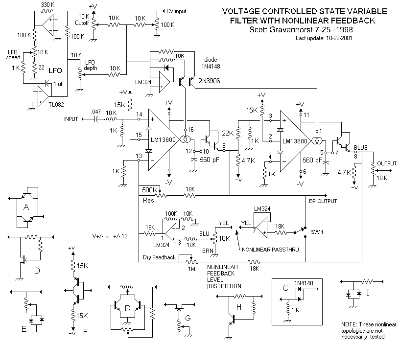
The schematic below is what I used to build a prototype for testing this idea.
Values of components are now stable.
My idea was to pass some linear feedback along with a controllable amount of nonlinearized feedback. The addition of linear feedback softens the effect. I have not tested all of the nonlinearities shown, but I found little difference in the effect other than ease of getting distortion when trying a few of them. I am currently using C with 1N4148 diodes and a 1 K resistor. My original concept was to put a small block of solderless breadboard on top of the unit to allow tinkering with the nonlinearity. This doesn't seem all that useful, so I have put the nonlinearity permanently into the circuit at the point labeled 'nonlinear passthru'. SW1 serves to switch the nonlinearity between the two feedback circuits in this otherwise state variable filter circuit. The effect is more pronounced as the res and dry feedback pots are turned to higher resistance. The nonlinearity level control could be labeled 'distortion'. Turning it all the way down allows this circuit to operate as a plain old SVF. Turning it up changes both the amount and to some degree character of the distortion sound. This circuit will, under certain circumstances, oscillate. The oscillation produces a very high level signal, so be careful. I found that it tends to go into oscillation more easily when either of the 2 linear feedback controls are brought to too low a resistance. I may at some time add resistors to prevent this. It's wise to test your settings at low volume. Regarding power supply: While on the bench, I powered this with +/- 15 volts. I found no difference in operation when I substituted the +/- 12 volt supply that I built onto the board. There were no changes required for operation at these two different supply voltages. As shown, the CV is expected to linear (v/hz). I have no way of testing an expo setup for this, but I am sure it would work if properly designed. Comments are welcome. |
